Motorola MICOR
High Band to 220 MHz Conversion
Receiver Mod
Exciter Mod
Exciter Filter Mod
Power Amplifier Mod
Low Pass Filter Mod
RECEIVER
Order Crystals from International Crystal Manufacturing (405)
236-3741.
Crystal formula: Fxtal = (Frx-11.7)/12
International Catalog Number: 161186
Motorola Channel Element: K1005A
Step 1: Remove Aux. RX board from rear and Aux. control Board
and set aside… They will not be reused.
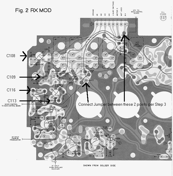
Step 2: Remove Main Rx board and replace the following components
with the values shown:
| C108 - 27pf NPO disk | C113 - 2.2pf NPO disk |
| C109 - 39pf N150 disk | C116 - 2.2pf NPO disk |
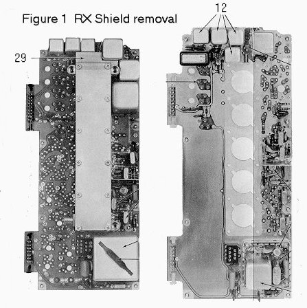
You need to remove the Metal shields from the 4 coils at the
rear end of the RX board to access these Caps.
Remove the 2 screws holding item 29, then remove item 29.
Unsolder 2 tabs on each of the item 12 shields
And remove.
Step 3: Connect Orange wire from Rx Board TP to location shown
in Fig. 2.
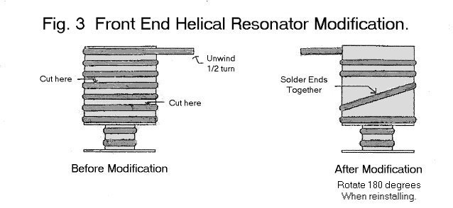
Step 4: Modify Helical resonator coils per Figure 3. The
resonators are held in with 2 screws each.
Remove resonator assembly from main RX board before attempting to
modify it.
Step 5: Reinstall Main RX board.
Step 6: Connect Coax that used to go to AUX RX board antenna
input to Main antenna input.
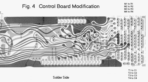
Step 7: Set channel jumpers on Control Board per figure 4.
Step 8: Tune per Motorola Manual.
NOTE: A GAASFET Preamp may be needed for
optimum sensitivity
.
EXCITER MODIFICATION
Order Crystals from International Crystal Manufacturing (405)
236-3741.
Crystal formula: Fxtal = Ftx/12
International Catalog Number: 161184Y
Motorola Channel Element: K1007A
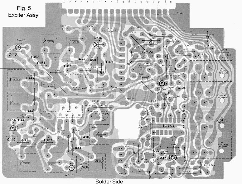
Step 1: Remove Exciter PCB and change the following components
to the new values shown:
| C430 – 68pf 5% Silver-Mica | C447 – 10pf NPO Disk |
| C433 – 150pf 5% Silver-Mica | C448 – 15pf NPO Disk |
| C434 – 120pf 5% Silver-Mica | C451 – 4.7pf NPO Disk |
| C437 – 22pf 5% Silver-Mica | C452 – 7.5pf NPO Disk |
| C439 – 22pf 5% Silver-Mica | C455 – 3.9pf NPO Disk |
| C440 – 47pf 5% Silver-Mica | C456 – 4.7pf NPO Disk |
| C443 – 15pf 5% Silver-Mica | C458 – 1.5pf NPO Disk |
| C444 – 12pf 5% Silver-Mica | C460 – 75pf 5% Silver-Mica |
| R429 - 180 ohm 1/2 watt |
Step 2: Reinstall Exciter PCB and tune in accordance with
Motorola manual.
Exciter should produce approximately 100mW.
Back to the top...
EXCITER FILTER (Z501)
This is Optional. The radio will operate without the filter in
line, but using this filter may reduce the white noise output of
the exciter.
There are 5 slug-tuned coils in this filter. It is symmetrical.
Step 1: Remove filter from the casting.
Step 2: Remove the cover from the filter.
Step 3: Remove 1 turn from the outermost coils in the filter
(coils connected to the input and output).
Step 4: Remove 1 turn from the center coil in the filter.
Step 5: Remove 2 turns from the remaining 2 coils.
Step 6: Tune the coils for minimum VSWR at the operating
frequency. Tuning will change when it is assembled, so make
an adjustment, then put the cover back on to check it.
Step 7: Re-assemble and re-install in the casting.
Back to the top...
POWER AMPLIFIER
Step 1: Remove the MICOR power amplifier PC Board and discard.
It is not tunable to 220MHz.
Save all hardware.
Step 2: Unsolder the wires from the Positive feedthrough
capacitor and unscrew it from the casting.
Step 3: Install the Positive feed through capacitor in the hole
next to the negative feedthrough.
Step 4: Re-connect the positive wire and filter cap to the
feedthrough.
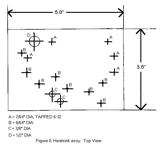
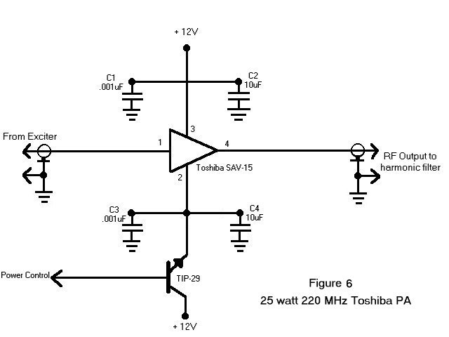
Step 5: Construct the Toshiba power module based amplifier per
the schematic. (fig 6)
And mount the module to a 3/16" thick X 3 ½" X 5"
aluminum plate where the
Original PA board was mounted (Fig. 8) Use
heat sink compound between the module
And plate, and between the plate and casting.
Step 6: Wire the PA to the Exciter output, +12V, Gnd., and to
the Harmonic filter.
Step 7: Wire the Blue power control wire to the Base of the pass
transistor
(Mounted where the old PA board Pass transistor was with new
insulators etc)
Back to the top...
LOW PASS FILTER
This modification changes the cutoff frequency of the harmonic
lowpass filter from 190 MHz to approximately 230 MHz.
Step 1: Remove the filter from the main casting by removing 4
screws.
Step 2: Remove the cover to the harmonic filter by removing the 2
screws on the rear of the unit.
Step 3: Remove 1 turn from the center of each coil, and solder
the 2 ends back together.
Stretch the coils to their original length and fine tune length
for minimum VSWR. (See Fig. 7)
Step 4: Re-assemble and re-install filter assembly in Radio.
The Radio should make 25-30 watts output and the
power control board should work exactly as it did with the
original PA.
Back to the top...
PA Heatsink Adapter Plate